

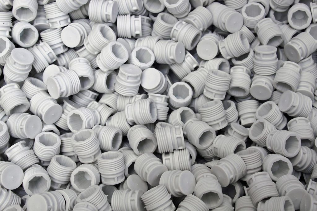
From implantable medical devices and surgical tools to aerospace sensors and micro-fluidics, modern engineering pushes components into sub-millimeter scales. Packaging constraints demand that critical pins, gears, valves, and fasteners deliver uncompromised reliability within fractions of a cubic millimeter.
- 1. The Physics of Scale: Why Miniaturization Isn't Just Scaling Down
- 2. Managing Tolerance Allocation and Stack-Up Geometry
- 3. Material Selection: When Grain Boundaries Match Feature Size
- 4. Eliminating Stress Concentrations in Fragile Micro-Features
- 5. Selecting the Right Fabrication Method to Avoid Tool Deflection
- 6. The Hidden Hazard of Micro-Burrs and Surface Roughness
- 7. Design for Micro-Manufacturability (DFM) and Metrology
Yet designing miniature parts isn't merely about scaling down a CAD model.
When physical dimensions drop into the micro-realm, standard mechanical assumptions break down. Surface friction, electrostatic forces, and micro-burrs dominate system behavior. A variance of two ten-thousandths of an inch—negligible on a pump housing—can seize a micro-gear train. Long-term reliability requires engineers to rethink material behavior, stress distribution, tolerance allocation, and fabrication methods. Here is how to engineer small components that perform dependably under demanding conditions.
1. The Physics of Scale: Why Miniaturization Isn't Just Scaling Down
The quick answer: As dimensions decrease, surface area shrinks slower than volume, amplifying the impact of surface tension, friction, and electrostatic forces over bulk mass and inertia.
Gravitational forces and mass drive mechanical calculations for macro-scale parts. However, the square-cube law alters how micro-components behave. As scale decreases, volume drops by the cube, while surface area drops only by the square.
In practical terms, the surface-to-volume ratio skyrockets. Inertia becomes negligible, while surface adhesion, friction, capillary action, and electrostatic charges become dominant forces.
A micro-valve moving effortlessly in simulation can stick in operation because surface tension from lubricant films exceeds actuation force. Engineers must design active clearance paths and low-friction coatings to prevent mechanical binding caused by surface phenomena.
2. Managing Tolerance Allocation and Stack-Up Geometry
The quick answer: Standard machining tolerances represent an unacceptably large percentage of a miniature part's total dimension, making rigorous GD&T and statistical stack-up analysis mandatory.
On a six-inch flange, a tolerance of ±0.005 inches represents less than one-tenth of one percent of total size. On a 0.050-inch micro-shaft, that same tolerance accounts for twenty percent of the feature.
Skipping a tight tolerance stack-up analysis leads directly to assembly failure. When micro-parts interface within an enclosure, accumulated variance causes interference, excessive backlash, or binding.
Engineers should adopt strict Geometric Dimensioning and Tolerancing (GD&T) principles, relying on true position, profile, and runout controls rather than linear plus-minus callouts. Specifying tight tolerances only on critical datum interfaces preserves production yields while guaranteeing flawless fit.
3. Material Selection: When Grain Boundaries Match Feature Size
The quick answer: In ultra-small features, individual material grain sizes approach the wall thickness of the component, transforming isotropic metals into unpredictable, anisotropic structures.
In macro-engineering, metals are treated as homogeneous, isotropic materials with uniform strength. That assumption holds when a wall contains thousands of crystalline grains.
However, if a micro-component features a wall thickness of 0.003 inches (75 microns), that cross-section may span only two or three metallic grain boundaries. At that scale, the orientation of a single grain dictates whether the wall flexes or fractures under tensile strain.
When designing miniature springs, flexures, or thin-walled tubes, specify fine-grain or ultra-fine-grain alloys, such as custom-melted titanium or specialized stainless steels. Tailored microstructures prevent localized grain cleavage and premature fatigue.
4. Eliminating Stress Concentrations in Fragile Micro-Features
The quick answer: Miniature components lack bulk material to absorb sudden peak loads, meaning sharp internal radii create extreme stress multipliers that trigger rapid cyclic fatigue.
Because micro-components have tiny cross-sectional areas, even modest working loads generate significant internal stresses. Sharp internal corners or abrupt transitions act as severe stress risers.
Preventing catastrophic miniature component stress concentrations requires disciplined geometric detailing:
- Generous Fillets: Replace sharp 90-degree internal corners with the largest feasible transition radius (at least 25% of adjacent wall thickness).
- Gradual Transitions: Taper wall thicknesses smoothly rather than stepping down abruptly to distribute bending loads.
- Under-Cut Reliefs: On micro-threaded shafts and bearing shoulders, incorporate stress-relieving undercuts to prevent stress localization at thread roots.
Smooth transition geometry ensures stress flows evenly, maximizing cyclic fatigue life without adding mass.
5. Selecting the Right Fabrication Method to Avoid Tool Deflection
The quick answer: Mechanical cutting tools flex, vibrate, and chatter when machining sub-millimeter walls; non-contact electrical discharge machining eliminates cutting forces and preserves micron tolerances.
Traditional CNC milling and turning face hard physical limits when producing micro-scale geometry. End mills smaller than 0.015 inches flex under cutting pressure, causing tool deflection, chatter marks, dimensional tapering, and tool breakage.
To achieve repeatable micro-features without mechanical stress, design teams turn to non-contact processes. Utilizing precision wire edm machining allows manufacturers to cut complex contours, micro-slots, and thin walls in hardened tool steels, carbide, and exotic alloys with tolerances tighter than ±0.0001 inches. Because wire EDM uses electrical sparks rather than mechanical contact, it imparts zero physical cutting force onto workpieces, preventing distortion and leaving pristine, burr-free edges.
6. The Hidden Hazard of Micro-Burrs and Surface Roughness
The quick answer: At sub-millimeter scales, standard edge burrs represent a major fraction of total component size, necessitating intentional edge breaks and controlled surface finishes.
On a large bracket, a 0.002-inch burr along an edge is harmless. On a micro-hydraulic spool valve, that same burr can obstruct ports, short-circuit electrical contacts, or shed particles that destroy sensitive seals.
Removing micro-burrs mechanically is difficult because abrasive methods can round off critical functional edges.
Designers must address edge conditions proactively on drawings:
- Define Burr Limits: Specify maximum allowable edge burrs (e.g., maximum 0.0005 inches) rather than using generic notes.
- Model Controlled Radii: Design 0.001- to 0.003-inch edge chamfers into the CAD model directly to guide tool paths.
- Plan for Chemical Deburring: Ensure part geometries allow fluid access for automated deburring methods like electropolishing or chemical etching.
7. Design for Micro-Manufacturability (DFM) and Metrology
The quick answer: If a micro-feature cannot be securely held in a fixture or verified with optical and coordinate metrology, it cannot be reliably manufactured at commercial scale.
A common pitfall in miniature engineering is designing features that look feasible on a zoomed-in CAD monitor but are impossible to fixture, handle, or measure in production.
Successful design for micro-manufacturability incorporates practical production and metrology constraints early:
- Fixturing References: Incorporate flat locating tabs or non-functional datum surfaces that allow operators to clamp and locate tiny blanks accurately.
- Assembly Alignment Aids: Include asymmetric locating pins or lead-in chamfers to guide micro-assembly under magnification without damaging fragile features.
- Optical Inspection Access: Avoid recessed, blind cavities that optical vision systems or laser confocal microscopes cannot measure directly.
Designing parts with clear optical sightlines ensures technicians verify critical dimensions rapidly without damaging delicate features.
Designing small components for dependable performance requires moving beyond conventional macro-scale intuition. When dimensions measure in thousandths of an inch, surface friction, grain orientation, stress concentrations, and tool mechanics exert outsized influence over component life. By designing with disciplined GD&T, selecting non-contact processes like wire EDM, eliminating sharp stress risers, and planning for deburring and metrology early, engineers turn intricate micro-designs into robust, reliable production realities.







1 thought on “Designing Small Components for Reliable Performance”